how to draw 3d sketch on solidworks
When creating 3D models for 3D printing, we recommend taking the 3D printing procedure into account at all times. Smart modeling prevents 3D printing imperfections, weak areas, and minimizes the use of support fabric.
Some tips:
-
Adding small fillets to internal corners makes the printed function much stronger.
-
The minimum wall thickness for stereolithography (SLA) 3D press is 0.6 mm, for selective laser sintering (SLS) 3D printers it is 0.8 mm, and a practiced minimum fused deposition modeling (FDM) wall thickness is 3 times the nozzle size, typically iii x 0.4 = one.two mm.
-
Horizontal bridges or spans over 21 mm require support material in SLA 3D printing. FDM 3D printers can commonly reproduce around l mm bridges without supports.
-
With SLA 3D printers, wires can exist very thin, upward to xx times the wire width. For example, with 0.3 mm thickness, y'all tin print up to seven mm tall before you start to see waving. ane.v mm wires can become up to xxx mm tall without defects. Usable wires in SLS first at 1 mm diameter and in FDM at four times the nozzle width.
-
For embossed details, stick to a minimum of 0.iv mm depth for SLA and SLS, and 0.6 mm for FDM.
-
For parts that are close together but require a slight separation, stick to a minimum of 0.5 mm clearance.
-
Proceed overhangs to a minimum or at least below a certain threshold bending for 3D printing without supports. For SLA, the threshold is nineteen degrees while for FDM, 45 degrees minimum needs to be attained. SLS 3D printers require no support material since the pulverization bed is cocky-supporting.
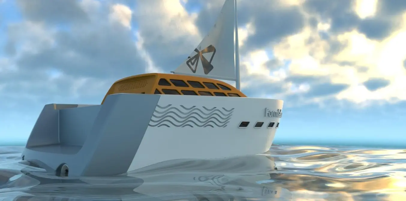
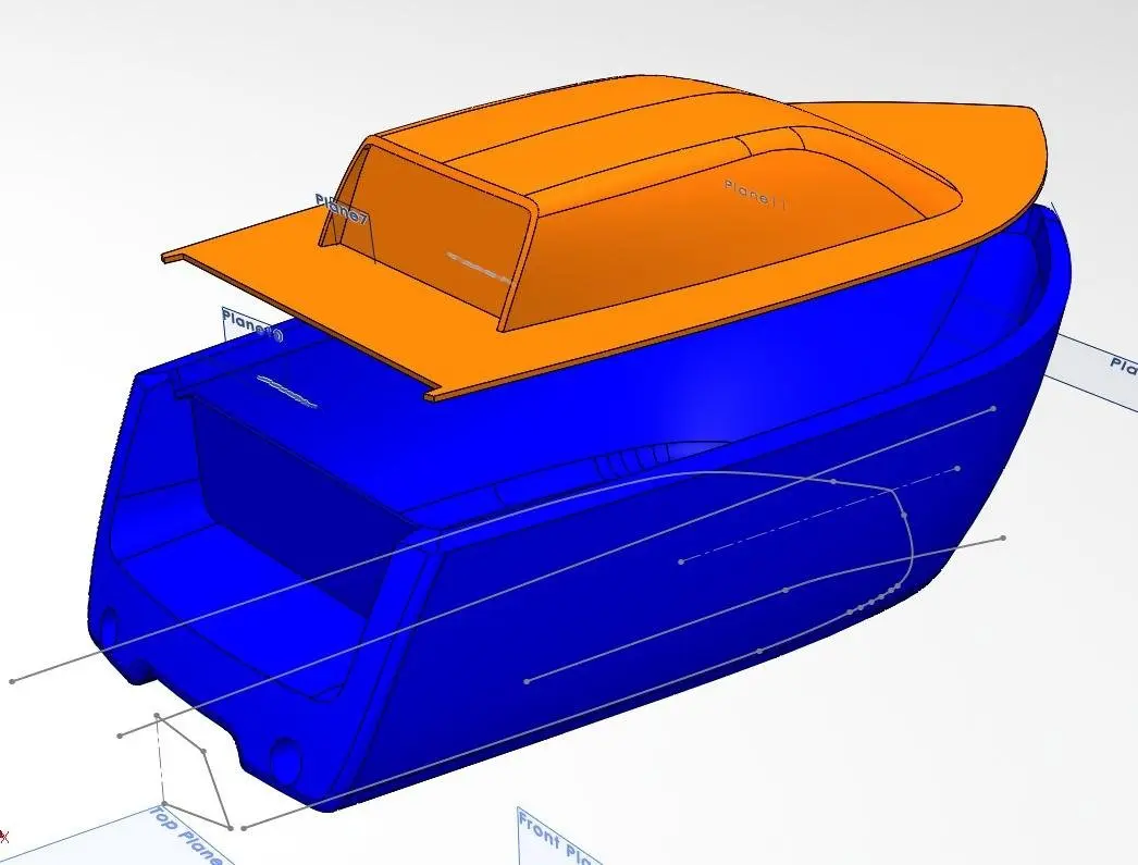
In our example, we are modeling a custom yacht model while keeping 3D press restrictions in mind. This model entails some relevant features that need to exist controlled to keep the model 3D printable, while offer avant-garde modeling challenges. Ane of these is the hull. Because of inner architecture requirements and hydrodynamics, a boat hull needs to exist tightly controlled at several sections and is therefore created using a surface loft with multiple profile curves at different planes along the length of the ship.
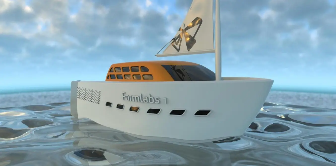
Our example custom yacht model creating modeled in Solidworks.
To create the topmost curve of the hull, we use the Projected Curve feature under Insert → Curve → Projected and select the Sketch On Sketch method. This creates a three-dimensional combination of ii dissimilar curves that are oriented on different planes. For the hull, an outline of the gunkhole shape drawn from the meridian was projected onto an upward sloping curve drawn from the side.
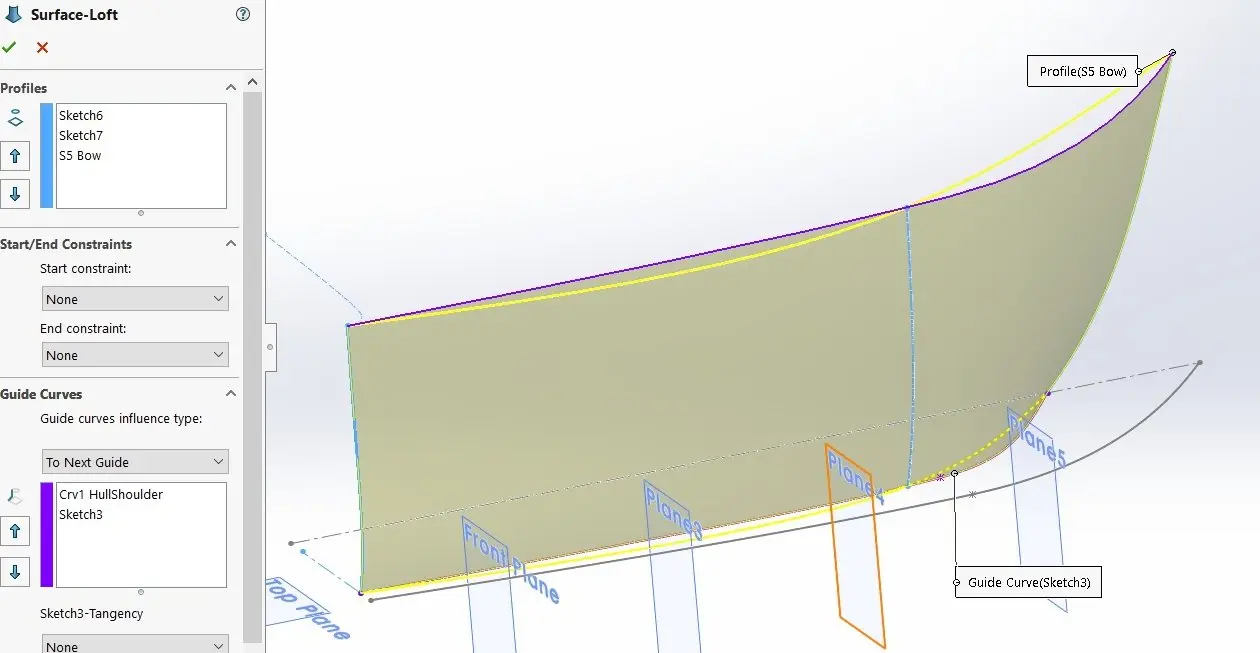
Lofting enables creating polish surfaces through multiple profile curves.
This lofting performance uses strictly divers curves at all sides plus profile curves. Using this many curves has to exist done advisedly because it will affect surface curvature. Another way to create surfaces is to create a loft betwixt two curves only. Keeping things unproblematic often results in better quality surfaces, which in plow leads to more robust and loftier-quality models.
To control the lofting direction, use either one guide curve or Start/End Constraints which can be set in the Loft carte. When using a guide curve, the 2 profile curves are typically fatigued on planes that are created perpendicular to the guide curve at its endpoints. When opting for Tangency or Curvature start and end constraints, utilize an extruded or ruled surface to define the lofting direction. Setting the kickoff and cease Tangent Length then allows precise control. Using this method, intersections between different surfaces will exist less defined and have to be created afterwards using trims or split lines, just the reward is superior surface continuity.
A sweep operation is similar in function to a loft but uses ane profile curve. A boundary surface is even more than similar to a loft with the divergence that information technology allows setting showtime/end tangency in both directions. The advantage is more than command but at the cost of overall surface curvature.
Lofting Pro Tip #1: To evaluate surface quality, check Curvature Combs and/or Zebra Stripes under Curvature Display at the bottom of the surface operation card.
Lofting Pro Tip #2: In the 3D viewport, correct-click and choose Show All Connectors. This allows the user more control over how different curves are continued, preventing undesired occurrences such equally torsions.
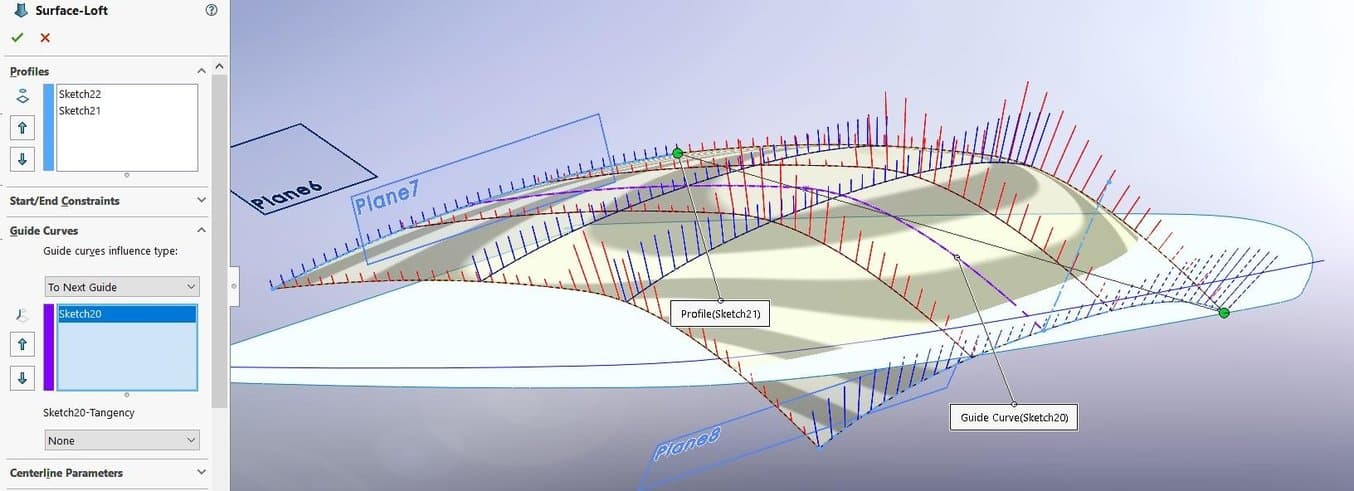
Lofting surfaces freely in space results in nifty surface continuity.
With the gross surfacing work completed, it is time to combine them together into volumes. In our yacht model, every side of both the hull and cabin superstructure has been created as a separate surface. At present when choosing Insert → Surface → Trim Surface, select the Mutual option and choose the surfaces to be combined. And so SolidWorks allows creating the parts of every surface to maintain or delete, and automatically stitching the remaining parts together into one single surface body.
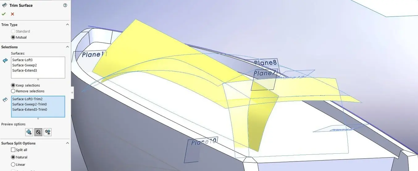
Trimming different lofted and swept surfaces together into a single volume.
All major surfaces have been created using lofting/sweeping and so trimming operations.
Creating an edge at an angle or perpendicular to the original surface is a pop design characteristic. The Ruled Surface characteristic under Insert → Surface → Ruled Surface allows that and offers the Tapered to Vector option. This allows picking a reference border as the direction vector and specifying an bending at which the ruled surface will be generated in relation to the reference vector. In the yacht model, both the border providing thickness to the elevation of the hull and the edge moving downwards to connect with the deck were created using a ruled surface. An alternative to the ruled surface is Radiate (Insert → Surface → Radiate). This creates an edge perpendicular to the base surface following an edge or carve up line on that surface.
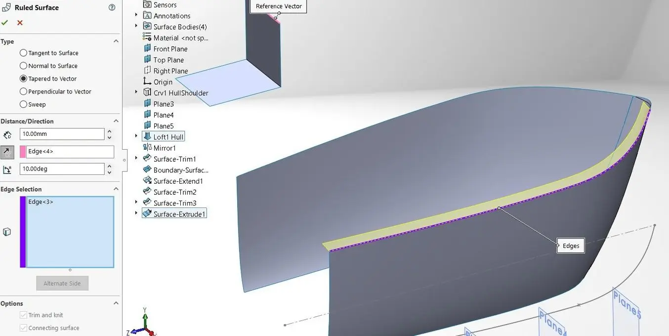
The Ruled Surface performance offers several options to create flanges.
Calculation fillets to a 3D printable model is recommended because they make the office stronger and less decumbent to crack forming. Additionally, they too catch the light and add to the aesthetic impression.
There are many ways to add fillets to a design:
-
Edge Fillet: Round
-
Edge Fillet: Conic Rho
-
Edge Fillet: Conic Radius
-
Edge Fillet: Curvature Continuous
-
Variable Radius Fillet
-
Face up Fillet
-
Full Circular Fillet
-
Hold Line Fillet / Alloy
A Round Fillet is the near bones, besides computationally speaking. Over 5 mm in size information technology will outcome in a visible line on manufactured items as an optical effect where the surface meets the fillet—for 3D press the maximum radius is slightly college considering the surface roughness hides imperfect surface continuities. The advantage of using Border Fillets is that every fillet can be simultaneously applied to multiple edges, whereas other fillet types have to be individually created for every border.
Conic Fillets have get increasingly popular among CAD designers equally the side by side best matter because they result in a smoothen blend while being computationally lightweight. The Conic Rho parameter here allows setting the 'peakiness' of the fillet.
Curvature Continuous Fillets are the most computationally intensive just effect in the highest quality.
A Variable Radius Fillet allows transitions in radius within the same fillet. This comes in handy when the fillet ends in a tight cusp where a very depression or zero radius fillet works and other types of fillets fail.
A Face Fillet creates a rounding between specified faces rather than edges–in some cases this results in a more robust fillet functioning. Checking the pick Constant Width sometimes creates meliorate results.
The Full Round Fillet is a specific type of face fillet that creates a total circular rounding between three faces such every bit the crosscut side of a thin solid. When modifying the geometry, the full circular fillet automatically scales along.
A Agree Line Fillet is a variation of the face fillet where not only the radius is specified, but likewise the lines where the surfaces involved encounter the fillet. This only works on solid bodies and the utilise of carve up lines typically results in successful hold line fillets. In case the surface is difficult to convert to a solid first for creating the hold line fillet, an culling arroyo is cut the surface open with trim lines, then blending the open sections together using a Loft functioning and using Insert → Surface → Knit to combine all surfaces back into a single surface trunk.
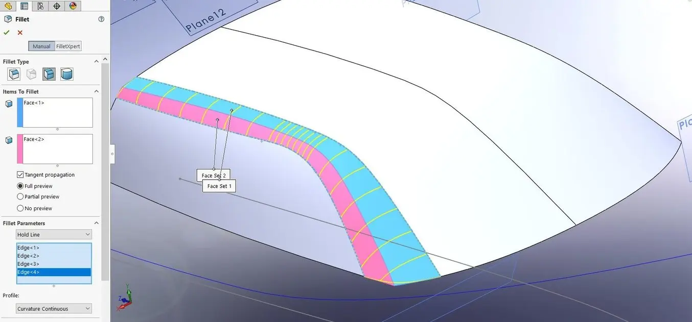
Apply Hold Line Fillets to create large blends betwixt surfaces.
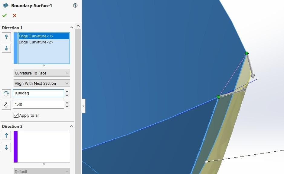
The bow front was filleted with a surfacing feature to optimize curvature.
It is preferable for 3D printing to create thin-walled models, because these also define the inside of the model instead of leaving information technology up to slicer software to create infill and wall thicknesses. When modelers accept attained a consummate surface model, it is necessary to convert these into solid bodies. Ornamental details such equally fillets and embossing are added after since these may impede the solidification process.
There are multiple workflows to go about converting surfaces to solids:
-
Knit to Solid: When all surfaces connect to enclose a volume, choose Insert → Surface → Knit Surface, then bank check Create Solid.
-
Thicken: Choose Insert → Boss/Base of operations → Thicken, check Create Solid from Enclosed Volume to generate a closed solid torso, uncheck it for a thin shell.
-
Trim to Solid: When all mutually trimmed surfaces result in an enclosed volume, these can be immediately converted to a solid past ticking the box Create Solid.
-
Offset: Create an kickoff surface that represents the inner wall with Insert → Surface → Commencement. Then it is possible to connect the edges using the Loft control. At present, instead of selecting a single border, select the unabridged edge boundary loops by right-clicking on the container box in the card under Profiles and choosing SelectionManager. Make sure to have the offset points of both edge loops at an adjacent position and you will exist able to loft the entire connexion in 1 swoop. With the inner surface and connecting edges selected, they can now be converted to a solid with a Knit to Solid procedure. An alternative to lofting is creating a ruled surface at an angle and so it intersects the inner surface, then using the Trim to Solid approach.
-
Beat: Subsequently having created a solid from an enclosed surface volume, thin walls can exist achieved with Insert → Features → Shell. This starts an advanced script that creates a hollow solid part ready for 3D printing.
For our 3D printed yacht, the deck including the superstructure is printed as a divide office from the hull. This is a logical separation because both parts have a flat surface that will largely print without whatever support fabric. Where surfaces include simply big fillets without small-scale details, the Thicken operation works well.
Surface bodies are turned into thin-walled solids with the Thicken command.
In several cases, designers and engineers desire to create carve up solid bodies, for example when applying different wall thicknesses to different parts of the model. To merge solids with each other, SolidWorks offers Boolean operations nether Insert → Features → Combine. To unify multiple parts into one, choose Add. Subtract will cutting out one shape from the other, while Common leaves but the function where multiple bodies overlap.
In Assembly Mode, it is also possible to combine split parts with the Join feature. First, create a new part with Insert → Component → New Part, so click Insert → Features → Join. This will unify selected parts within the assembly at their current position and orientation into one single body.
The best way to divide a solid body into ii sections is by using the Split command under Insert → Features → Split. First, create the cutting surface—it can have whatsoever shape and can even exist a sketch. Then striking Cut Part and decide in the Resulting Bodies panel which ones to go on. In case of requiring but one function to be retained, an alternative is the Cut with Surface control under Insert → Cut → With Surface.
Pro Tip: Save out an individual body of the design as a carve up SolidWorks .SLDPRT file with Insert → Features → Relieve Bodies. To go along a reference to the original office so that the blueprint volition be automatically updated in sync with the original model, create a Derived Role past right-clicking the body in the FeatureManager and select Insert into New Part.
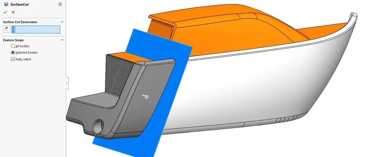
A cutting surface divides the model into ii separate solids.
For parts of the model that are spaced apart, go out at to the lowest degree 0.v mm clearance to ensure they do not fuse together during 3D press. When 3D press multiple parts that demand to be fitted together, such as the hull and deck in our project, information technology is important to adhere to expert tolerancing practices. For a snug fit, get out 0.25 mm clearance for parts created with FDM, and 0.15 mm for SLS, and SLA.
Offsets are the go-to mode for creating distances betwixt related features. Likewise offsetting surfaces (Insert → Surface → Starting time) it is likewise possible to create a sketch as an first from an existing sketch or edge. To offset a sketch, open a new sketch, select the original one, and click on Commencement Entities. For offsetting but a role of the original sketch, or offsetting edges in the model, kickoff import these to your sketch with Convert Entities. With the imported entities selected check Construction Geometry to bespeak that these are non the sketches to be used for the feature but an in-betwixt footstep. At present select the parts to offset and hit First Entities.
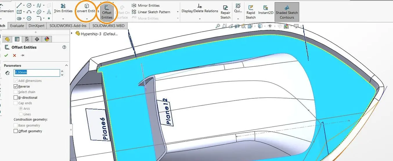
Utilize First features for creating clearances between different 3D printed parts.
Offsets are also skilful for negative clearances, that is when features demand to overlap. Consider for example the case of calculation ribs to the inner hull. Ribs are an attainable method to add strength to the part at specific locations. For whatsoever curved surface, we cannot merely draw a curve on the surface and extrude information technology to create a rib, because it would not connect to the original surface in all places. To ensure a consequent overlap, nosotros need to first information technology into the solid body just enough and so the extrusion will overlap on all sides. An beginning bend tin exist created at a department plane to the original surface, and then using the Intersect option under Insert → Curve → Split Line and selecting the section aeroplane and surface. Now create a new sketch on the department plane and offset the split line to create the first curve. Finally, draw the unabridged feature so it can be extruded.
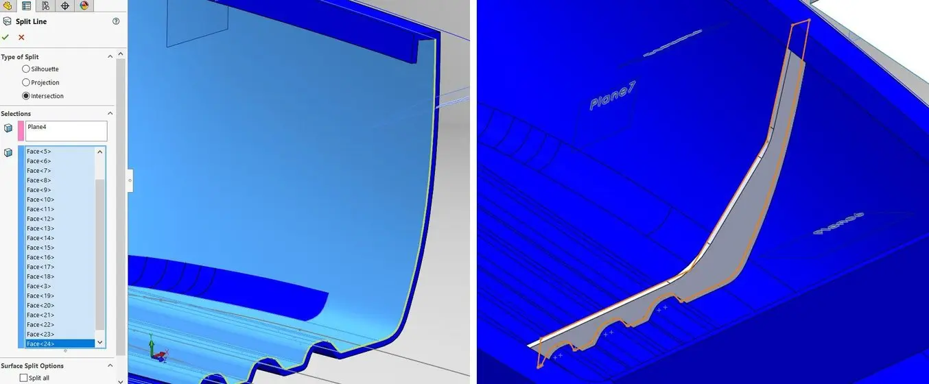
A negative starting time creates overlapping features that tin can be merged into a single part.
SolidWorks provides aplenty opportunities for adding three-dimensional text features to a design. Most font types will be readily convertible into SolidWorks, with a preference for Sans Serifs. Lettering tin can be added to a sketch using Tools → Sketch Entities → Text. Text can exist mapped to follow a curve, information technology can exist mirrored, and individual letters can exist rotated under a specified angle.
A specific method applies to mapping text onto curved surfaces: text wrapping. This repositions text drawn on a planar surface onto a curved, preferably cylindrical, one. In order to guess the hull'due south shape, draw an arc sketch on the height plane all-time matching the curvature of the hull, so extrude the sketch. Create the text feature on a plane or planar surface facing the curved extrusion. Now wrap information technology onto the cylindrical surface with Insert → Features → Wrap. The text is at present scribed onto the surface and divides information technology into unlike faces. If nosotros delete the faces surrounding the messages besides as the openings (known as 'eyes' in typography), simply the letters remain. These will then exist individually converted into a solid using the Thicken command and positioned onto the hull with Insert → Features → Move/Copy.
Now with an offset of the hull surface and the Cut with Surface control equally mentioned in the section Working with Multiple Solids, the text can be cut then its outer surface exactly follows that of the hull. The reason why nosotros did not choice the more advanced Spline Surface wrap method is that using a cylindrical wrap maintains the horizontal orientation of the text where otherwise information technology would exist oriented downwards along the hull's normal vectors. Notation that when wrapping straight onto a solid body, it is possible to immediately emboss or deboss the text into the solid.
Pro Tip: Utilise a maximum sideways protrusion of one mm for lettering for back up-complimentary 3D press. The minimum legible particular for SLA 3D press is 0.ane mm for embossing and 0.iv mm for engraving, 0.35 mm for SLS, and 0.6 mm for FDM.
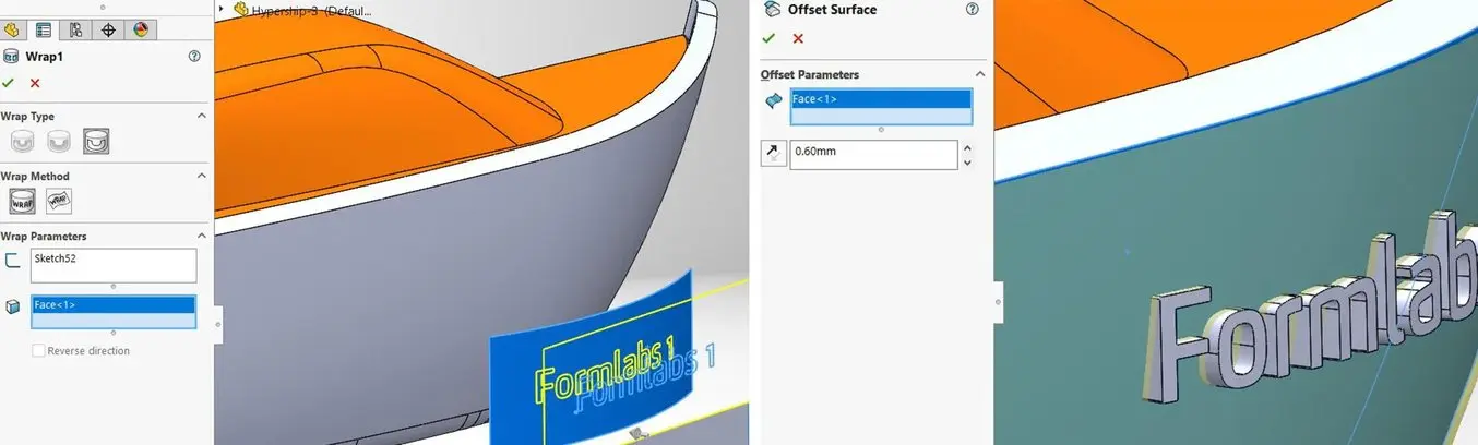
The wrap function offers advanced ways of calculation text to surfaces.
The preferred way of creating grooves on a solid body is the Sweep operation under Insert → Cutting → Sweep. Every sweep needs a guide bend and profile curve. A guide curve on a planar surface tin be directly sketched onto that surface, but for a curved surface, nosotros need to create a projected curve or split line. The choice Circular Profile merely creates a tube forth the guide curve. With the option Solid Profile, it is possible to pick a solid body to generate the cut and emulate a CNC cutting tool. With a custom Sketch Profile, it is possible to install an additional twist value, so the finish of the swept groove will be at a different specified angle than the start.
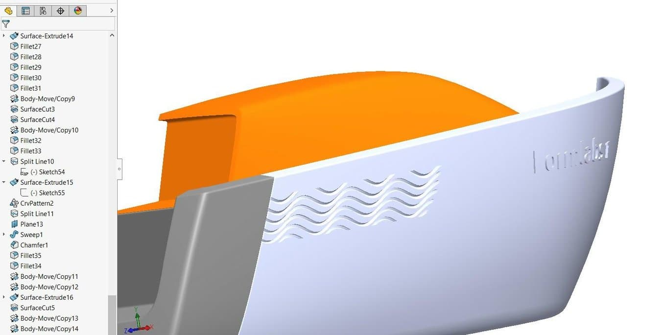
In our instance, nosotros have swept a square over a sinusoidal split up line on the gunkhole hull. The foursquare is positioned at a 45-caste bending relative to the guide curve in society to enable printing without stark overhangs. For an exact design, every separate line volition take to be provided with its own sweep. For the minor cut off elements at the edge of the patterning area, it is acceptable in some cases to copy and translate the nearest swept solid torso, and cut it with the bend that defined the original patterning area using the Cut with Surface control.
Pro Tip: The sinusoidal curve was created by choosing Equation Driven Curve under splines in the sketch tab. This allows designers to input XY functions that directly generate a spline. For an advanced option, information technology is possible in SolidWorks to gear up a gear up of variables and drive these using Excel worksheets.
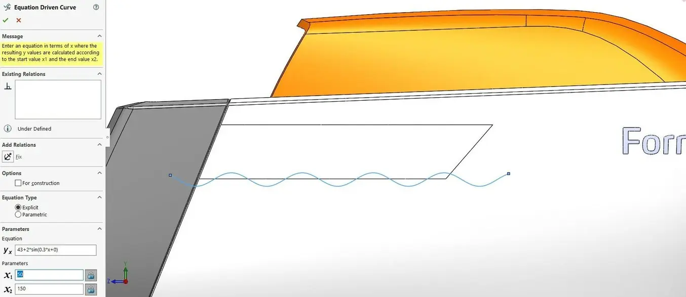
Apply Equation Driven Bend for mathematically divers sketches.
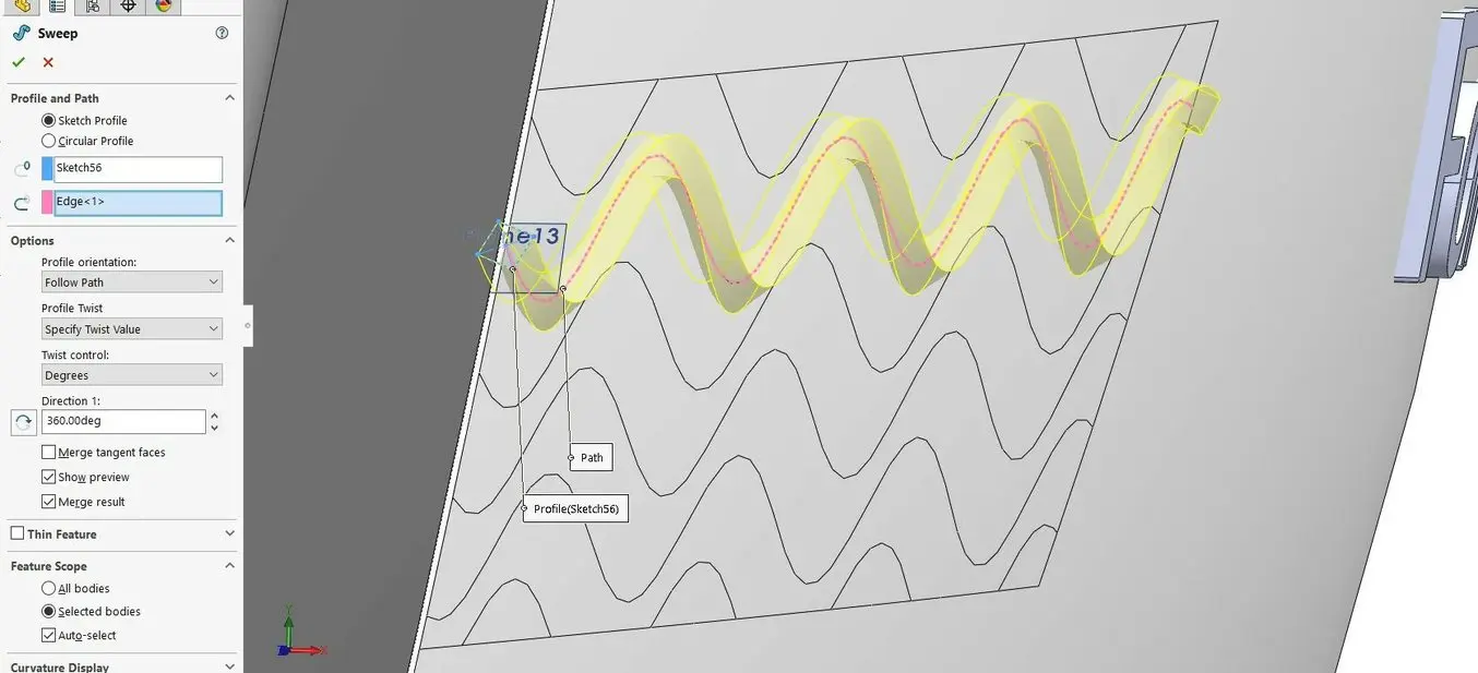
Twisted sinusoidal sweeps making for a three-dimensional graphic surface area on the hull.
Designing patterns manually tin exist a bit boring. In SolidWorks, it could non be simpler creating a linear or rotational pattern of an object or feature with the Insert → Design/Mirror → Linear Design and Insert → Pattern/Mirror → Circular Pattern commands. Information technology is likewise possible to provide a numerical linear translation or rotation when using the Insert → Features → Motion/Copy command and ticking the Copy box with the number of copies chosen.
If we project a curve onto a solid body every bit a Split Line, we tin can blueprint another solid body such equally a window forth that curve, even maintaining the normal management to correctly orient every case on the curve. To practice that, choose Insert → Design/Mirror → Curve-Driven Pattern and tick the radio box for the Tangent to Bend alignment method. If spacings need to be uneven, it is possible to define the locations using points in a dissever sketch and opting for a Sketch-Driven Pattern under Insert → Blueprint/Mirror → Sketch-Driven Pattern. Going beyond that, information technology is fifty-fifty possible to generate point locations within a sketch by linking a mathematics-driven Microsoft Excel sheet or from a text file containing the coordinates using the Insert → Design/Mirror → Tabular array-Driven Pattern functioning. This type of parametric control enables designers to generate the geometrically complex and organic features that 3D printing excels at.

Curve-driven patterns work to create repeated elements on a complex shape.
Another overnice characteristic is the Fill up Blueprint, accessible nether Insert → Pattern/Mirror → Fill Pattern. The first step is to ascertain an surface area to exist filled with patterned elements. Next, choose a patterning layout and spacing dimensions. This is an automated manner to create graphically interesting perforations for parts similar speakers, air vents, and showerheads. Further customization is possible past selecting the Instances to Skip at the lesser of the Fill Pattern bill of fare.
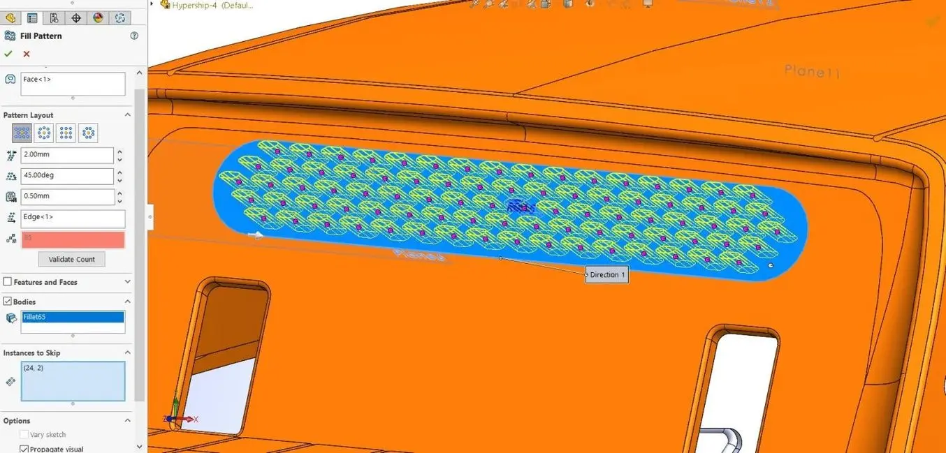
Make full Pattern automatically generates graphically interesting perforations.
The Flex feature is an odd one out in SolidWorks considering it is not driven by sketches, and yet, it results in workable geometry that cannot exist generated otherwise. Accessing it under Insert → Features → Flex enables the designer to bend, twist, taper, and stretch solid and surface bodies afterward they have been modeled. These features also stack upwards successively for increasingly circuitous surfaces. Additional control on the eye pivot location of the twist, taper, or bend can exist achieved using a control triad. This requires creating a Coordinate Arrangement reference first by clicking Insert → Reference Geometry → Coordinate System. The triad can be relocated by selecting an element to move information technology to in the 3D viewport, then hitting the right mouse button on the center of the triad, then Move to Selection. Moving the Trim Planes then allows angle merely a specific portion of the model.
Another post-surfacing performance is Freeform (Insert → Features → Freeform), where the designer tin can add together control points on section curves across a complex surface. These points, too equally the kickoff and end curvature direction of the section curves, can and then exist individually modified allowing organic and unusual surface shapes to exist made.
Deform, under Insert → Features → Deform, will morph a shape from a reference point or surface, in a detail management and with a specific elasticity (the Stiffness pick). The Curve to Curve mode accurately transforms 1 curve within the part to a newly created curve then the part gains an entirely new shape. In Surface Push button mode, a split surface is used as a postage stamp that near deforms the office by pressing into information technology.
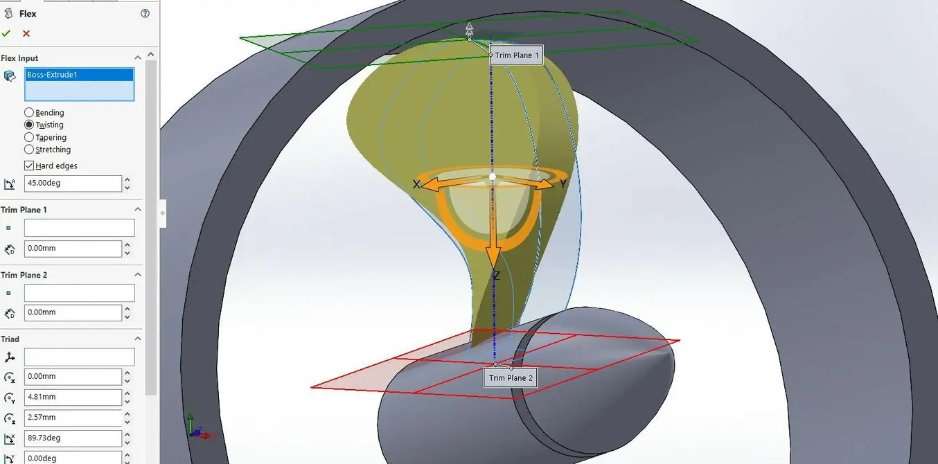
Flex is a post-processing operation to bend, twist, and taper bodies like this propeller.
armstrongsaidgety.blogspot.com
Source: https://formlabs.com/blog/solidworks-tutorial-3d-printing-modeling-inspection/
0 Response to "how to draw 3d sketch on solidworks"
Post a Comment